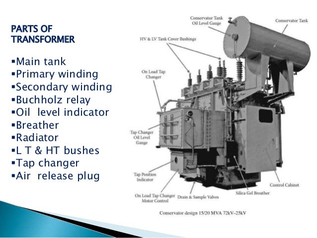
Transformer parts and functions
1.Buchholz relay:
It is a very sensitive gas and oil operated instruments which safely detect the formation of gas or sudden pressure inside the oil transformer.
2.Conservator:
It is used to provide adequate space for the expansion of oil when transformer is loaded or ampient temperature changes.
3.Silica gel breather:
It sucks the moisture from the air which is taken by transformer so that dry air is taken by transformer .
4.Double diaphragm explosion vent:
It is Used to discharge excess pressure in the atmosphere when excess pressure is developed inside the transformer during loading.
5.Oil level indicator:
It is used to show the oil level in the transformer.
6.Winding temperature indicator:
It is used to show the temperature of transformer winding.
7.Radiator:
These are used for cooling of the transformer oil.
The supply voltage is connected to the primary winding the load is connected to primary winding the load is connected to the secondary winding and in the transformer core only the magnetic flex path will be established in the power transformer on load tap changer used but in distribution transformer off circuit tap changer are used.
Sunday, April 23, 2017
Monday, April 10, 2017
Electrical Direct online motor starter(DOL)

Electrical DOL starter(Direct online starter)


.
Friday, March 17, 2017
Electric motors
What is Electric motors
Electric motor is an electrical machine that converts to electrical energy to mechanical energy. The reverse of this would be the conversion of mechanical energy into electrical energy and is done by an electric generator.

Wednesday, March 15, 2017
Electric cable gland selection following points
Electric cable gland selection
Gland should be selected on following Points
Gland should be selected on following Points
- Type of Cable
- Gland Size
- Entry Type/Thread Specification of application
- Ingress Protection required.
- Material
Electric cable types and details
Types of Electrical Cables –
There are more than 20 different types of cables available today, designed for applications ranging from transmission to heavy industrial use. Some of the most commonly-used ones include:.
Non-Metallic Sheathed Cable :
These cables are also known as non-metallic building wire or NM cables. They feature a flexible plastic jacket with two to four wires (TECK cables are covered with thermoplastic insulation) and a bare wire for grounding. Special varieties of this cable are used for underground or outdoor use, but NM-B and NM-C non-metallic sheathed cables are the most common form of indoor residential cabling.
Underground Feeder Cable :
These cables are quite similar to NM cables, but instead of each wire being individually wrapped in thermoplastic, wires are grouped together and embedded in the flexible material. Available in a variety of gauge sizes, UF cables are often used for outdoor lighting and in-ground applications. Their high water-resistance makes them ideal for damp areas like gardens as well as open-to-air lamps, pumps, etc.
Metallic Sheathed Cable : Also known as armored or BX cables, metal-sheathed cables are often used to supply mains electricity or for large appliances. They feature three plain stranded copper wires (one wire for the current, one grounding wire and one neutral wire) that are insulated with cross-linked polyethylene, PVC bedding and a black PVC sheathing. BX cables with steel wire sheathing are often used for outdoor applications and high-stress installations.
Multi-Conductor Cable :
This is a cable type that is commonly used in homes, since it is simple to use and well-insulated. Multi-conductor or multi-core (MC) cables feature more than one conductor, each of which is insulated individually. In addition, an outer insulation layer is added for extra security. Different varieties are used in industries, like the audio multicore ‘snake cable’ used in the music industry.
Coaxial Cable :
A coaxial cable features a tubular insulating layer that protects an inner conductor which is further surrounded by a tubular conducting shield, and might also feature an outer sheath for extra insulation. Called ‘coaxial’ since the two inner shields share the same geometric axis, these cables are normally used for carrying television signals and connecting video equipment.
Unshielded Twisted Pair Cable :
Like the name suggests, this type consists of two wires that are twisted together. The individual wires are not insulated, which makes this cable perfect for signal transmission and video applications. Since they are more affordable than coaxial or optical fiber cables, UTP cables are often used in telephones, security cameras and data networks. For indoor use, UTP cables with copper wires or solid copper cores are a popular choice, since they are flexible and can be easily bent for in-wall installation.
Ribbon Cable :
Ribbon cables are often used in computers and peripherals, with various conducting wires that run parallel to each other on a flat plane, leading to a visual resemblance to flat ribbons. These cables are quite flexible and can only handle low voltage applications.
Direct-Buried Cable : Also known as DBCs, these cables are specially-designed coaxial or bundled fiber-optic cables, which do not require any added sheathing, insulation or piping before being buried underground. They feature a heavy metal core with many layers of banded metal sheathing, heavy rubber coverings, shock-absorbing gel and waterproof wrapped thread-fortified tape. High tolerance to temperature changes, moisture and other environmental factors makes them a popular choice for transmission or communication requirements.
Twin-Lead Cable :
These are flat two-wire cables that are used for transmission between an antenna and receiver, like TV and radio.
Twin axial Cable :
This is a variant of coaxial cables, which features two inner conductors instead of one and is used for very-short
Difference between cable and wire
Difference between cable and wire
"A wire is a single conductor. Cable is two or more insulated wires wrapped in one jacket .Multiple conductors that have no insulation around would be classified as a single conductor".
Tuesday, March 14, 2017
Electric transformer defenation
Electric Transformer
Definition of Transformer
Electrical power transformer is a static device which transforms electrical energy from one circuit to another without any direct electrical connection and with the help of mutual induction between two windings. It transforms power from one circuit to another without changing its frequency but may be in different voltage level. This is a very short and simple definition of transformer, as we will go through this portion of tutorial related to electrical power transformer, we will understand more clearly and deeply "what is transformer ?" and basic theory of transformer.
Working Principle of Transformer
The working principle of transformer is very simple. It depends upon Faraday's law of electromagnetic induction. Actually, mutual induction between two or more winding is responsible for transformation action in an electrical transformer.
Faraday's Laws of Electromagnetic Induction
According to these Faraday's laws, "Rate of change of flux linkage with respect to time is directly proportional to the induced EMF in a conductor or coil".

Basic Theory of Transformer
Say you have one winding which is supplied by an alternating electrical source. The alternating current through the winding produces a continually changing flux or alternating flux that surrounds the winding. If any other winding is brought nearer to the previous one, obviously some portion of this flux will link with the second. As this flux is continually changing in its amplitude and direction, there must be a change in flux linkage in the second winding or coil. According to Faraday's law of electromagnetic induction, there must be an EMF induced in the second. If the circuit of the later winding is closed, there must be an current flowing through it. This is the simplest form of electrical power transformer and this is the most basic of working principle of transformer. For better understanding, we are trying to repeat the above explanation in a more brief way here. Whenever we apply alternating current to an electric coil, there will be an alternating flux surrounding that coil. Now if we bring another coil near the first one, there will be an alternating flux linkage with that second coil. As the flux is alternating, there will be obviously a rate of change in flux linkage with respect to time in the second coil. Naturally emf will be induced in it as per Faraday's law of electromagnetic induction. This is the most basic concept of the theory of transformer.
The winding which takes electrical power from the source, is generally known as primary winding of transformer. Here in our above example it is first winding. The winding which gives the desired output voltage due to mutual induction in the transformer, is commonly known as secondary winding of transformer. Here in our example it is second winding. The above mentioned form of transformer is theoretically possible but not practically, because in open air very tiny portion of the flux of the first winding will link with second; so the current that flows through the closed circuit of later, will be so small in amount that it will be difficult to measure. The rate of change of flux linkage depends upon the amount of linked flux with the second winding. So, it is desired to be linked to almost all flux of primary winding to the secondary winding. This is effectively and efficiently done by placing one low reluctance path common to both of the winding. This low reluctance path is core of transformer, through which maximum number of flux produced by the primary is passed through and linked with the secondary winding. This is the most basic theory of transformer.
Main Constructional Parts of Transformer
The three main parts of a transformer are,
Primary Winding of Transformer- which produces magnetic flux when it is connected to electrical source.
Magnetic Core of Transformer- the magnetic flux produced by the primary winding, that will pass through this low reluctance path linked with secondary winding and create a closed magnetic circuit.

Definition of Transformer
Electrical power transformer is a static device which transforms electrical energy from one circuit to another without any direct electrical connection and with the help of mutual induction between two windings. It transforms power from one circuit to another without changing its frequency but may be in different voltage level. This is a very short and simple definition of transformer, as we will go through this portion of tutorial related to electrical power transformer, we will understand more clearly and deeply "what is transformer ?" and basic theory of transformer.
Working Principle of Transformer
The working principle of transformer is very simple. It depends upon Faraday's law of electromagnetic induction. Actually, mutual induction between two or more winding is responsible for transformation action in an electrical transformer.
Faraday's Laws of Electromagnetic Induction
According to these Faraday's laws, "Rate of change of flux linkage with respect to time is directly proportional to the induced EMF in a conductor or coil".

Basic Theory of Transformer
Say you have one winding which is supplied by an alternating electrical source. The alternating current through the winding produces a continually changing flux or alternating flux that surrounds the winding. If any other winding is brought nearer to the previous one, obviously some portion of this flux will link with the second. As this flux is continually changing in its amplitude and direction, there must be a change in flux linkage in the second winding or coil. According to Faraday's law of electromagnetic induction, there must be an EMF induced in the second. If the circuit of the later winding is closed, there must be an current flowing through it. This is the simplest form of electrical power transformer and this is the most basic of working principle of transformer. For better understanding, we are trying to repeat the above explanation in a more brief way here. Whenever we apply alternating current to an electric coil, there will be an alternating flux surrounding that coil. Now if we bring another coil near the first one, there will be an alternating flux linkage with
that second coil. As the flux is alternating, there will be obviously a rate of change in flux linkage with respect to time in the second coil. Naturally emf will be induced in it as per Faraday's law of electromagnetic induction. This is the most basic concept of the theory of transformer.The winding which takes electrical power from the source, is generally known as primary winding of transformer. Here in our above example it is first winding. The winding which gives the desired output voltage due to mutual induction in the transformer, is commonly known as secondary winding of transformer. Here in our example it is second winding. The above mentioned form of transformer is theoretically possible but not practically, because in open air very tiny portion of the flux of the first winding will link with second; so the current that flows through the closed circuit of later, will be so small in amount that it will be difficult to measure. The rate of change of flux linkage depends upon the amount of linked flux with the second winding. So, it is desired to be linked to almost all flux of primary winding to the secondary winding. This is effectively and efficiently done by placing one low reluctance path common to both of the winding. This low reluctance path is core of transformer, through which maximum number of flux produced by the primary is passed through and linked with the secondary winding. This is the most basic theory of transformer.
Main Constructional Parts of Transformer
The three main parts of a transformer are,
Primary Winding of Transformer- which produces magnetic flux when it is connected to electrical source.
Magnetic Core of Transformer- the magnetic flux produced by the primary winding, that will pass through this low reluctance path linked with secondary winding and create a closed magnetic circuit.

Subscribe to:
Comments (Atom)